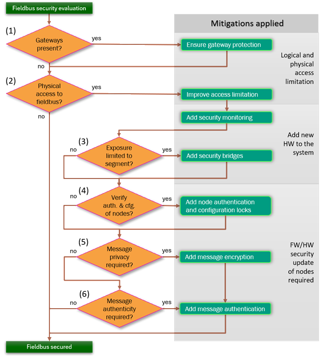
Mitigation Flowchart
Our six-step flowchart gives first guidance on which CAN security mitigations to apply. Each step poses one question about your system, and the answer points to the control to add before you move on. The questions run from the least invasive change, protecting an existing gateway or limiting physical access, to the most invasive, updating node firmware to add authentication and possibly encryption. Our goal is that you add only what your exposure requires.


Start Here If You Do Not Know Where to Start
If you have not yet decided which mitigations your CAN or CAN
FD system needs, work down the six questions in the flowchart
below to get first guidance. Each numbered decision asks one
thing about your system. The answer points to a potential
control to add before moving on. The order is deliberate. The
earlier steps protect what is already there and limit who can
reach the bus, the middle step reshapes the network, and the
later steps change the nodes themselves. The annotations on
the right of the chart show the rising cost of each band:
logical and physical access limitation first, then additional
hardware, then a firmware or hardware security update of the
nodes.
Treat the result as first guidance, then confirm it with a
structured risk
assessment.
0. Secure Bootloader Comes First
This step carries the number zero because it is not really a
question. The flowchart branches on properties of your system,
but a secure bootloader is required anyway, so it sits before
step one rather than inside the chart. The CRA
requires that vulnerabilities can be fixed through security
updates, and IEC
62443 expects authenticated firmware update and secure
boot. An update channel that does not authenticate what it
installs becomes the easiest way to defeat every control you
add later. For a product in scope of the CRA or IEC 62443 you
therefore do not really have a choice: put an authenticated
bootloader and secure boot in place first, then work through
the six questions below.
See Secure
Bootloader.
1. Protect the Gateways
The first question in the chart asks whether the system has
any gateways. A gateway is any node that bridges the CAN
network to any other network, such as a backend system, a
remote-service link or just another neighboring fieldbus.
Where they exist, they are exposed entry points, because an
attacker who never touches the wiring can still reach the bus
through them. If the answer is yes, ensure gateway protection
before anything else: harden the gateways, authenticate what
crosses them, and treat them as the boundary of trust.
See Secure
Gateways and Access
Limitation.
2. Limit Physical Access and Security Event Monitoring
The second step asks whether anyone can gain physical access
to the CAN bus, its wiring, or its connectors. If a person can
reach the bus, they can listen to every frame and inject their
own, so this question matters even when no gateway exists. The
chart gives two responses. First, verify if you can improve
access limitation so the wiring and connectors are harder to
reach. Second, add security monitoring so that tampering and
abnormal traffic are detected rather than silent.
See Access
Limitation, Bus
Load Monitoring and Anomaly Event
Monitoring.
3. Contain Exposure to a Segment
The third step asks whether the exposure identified so far is
limited to one segment. If it is not, the exposed portion of
the network can be used to reach all nodes. The mitigation is
to add security bridges: divide the system into zones by risk
profile and place controlled bridges between them, so
classical CAN can stay where the wiring is physically
protected while exposed areas sit behind a bridge running a
secure protocol. This is the first step that adds new hardware
to the system.
See Zoning /
Segmentation.
4. Authenticate Nodes and Lock Configuration
The fourth step asks whether you need to verify the
authenticity and configuration of the nodes themselves, that
is, to be certain which node sent a given message and that its
settings have not been altered. If so, add node authentication
and configuration locks as provided by SOFA. Authenticated
access to configuration objects keeps parameters and
calibration data from being changed by an unauthorized party.
From this step onward the chart notes that a firmware or
hardware security update of the affected nodes is required.
See Secure
Object Fieldbus Access.
5. Encrypt Messages That Need Privacy
This step asks whether message contents must remain private.
Some process data, calibration values, or key material must
not be readable by anyone listening on the bus. If privacy is
required, add message encryption on the frame level.
Authenticated encryption on each protected frame keeps its
payload confidential while also detecting tampering, so
confidentiality and integrity come together rather than as
separate add-ons.
See Frame Security.
6. Authenticate Messages That Need Integrity
The last step asks whether message authenticity must be
guaranteed without confidentiality, so that a receiver can
confirm a frame is genuine and unmodified rather than injected
or replayed. If so, add message authentication only. An
authentication tag on each protected frame lets receivers
reject anything that was not sent by a legitimate, keyed node.
See Frame
Security.
Frequently Asked Questions
How do I use this mitigation flowchart?
Work down the six steps in order. Each step poses one question about your system, and the answer points to the control to add. The steps are ordered from the least invasive change, such as protecting an existing gateway or limiting physical access, to the most invasive, such as updating node firmware to add authentication, so you add only what your exposure actually requires.
Do I have to apply every step?
No. Each step is conditional on a property of your system. If there is no gateway, step 1 does not apply. If the bus is already confined to a protected segment, step 3 adds nothing. The flowchart is first guidance for teams who do not yet know which controls they need, not a mandatory checklist. A full risk assessment refines and confirms the result.
Where does this flowchart fit with the rest of the site?
It is an entry point into the Solutions catalog. Each step links to the control that implements it, and the catalog carries the full threat-by-control matrix. For how to combine several controls into layered protection for a given IEC 62443 security level, see Defense in Depth under Risk Assessment.